For those, with that combination at home and searched for a simple and structured setup without many visible cables floating around: Thats for you!
I’ve integrated the RPI (3b), the power supply for it (230v AC to 5v DC 2A) and a 24v to 5v buck converter in the stock housing of the ender 5, as a bonus without a USB cable outside 😉
The BTT SKR Mini E3 is a good and easy replacement for original Creality Boards but somehow bitchy board. The most common problem here is, the limited PROGMEM of 256kb and no EEPROM… but what does this mean? Well at least, no Unified Bed Leveling for us (yet) and a bit more tweaking of available space and EEPROM Emulation. At writing time there was no stable solution to use the SDCard as EEPROM storage. The maximum marlin size is currently 224kb, keep that in mind!
As you can see here, this is my current setup inside the electronic box:
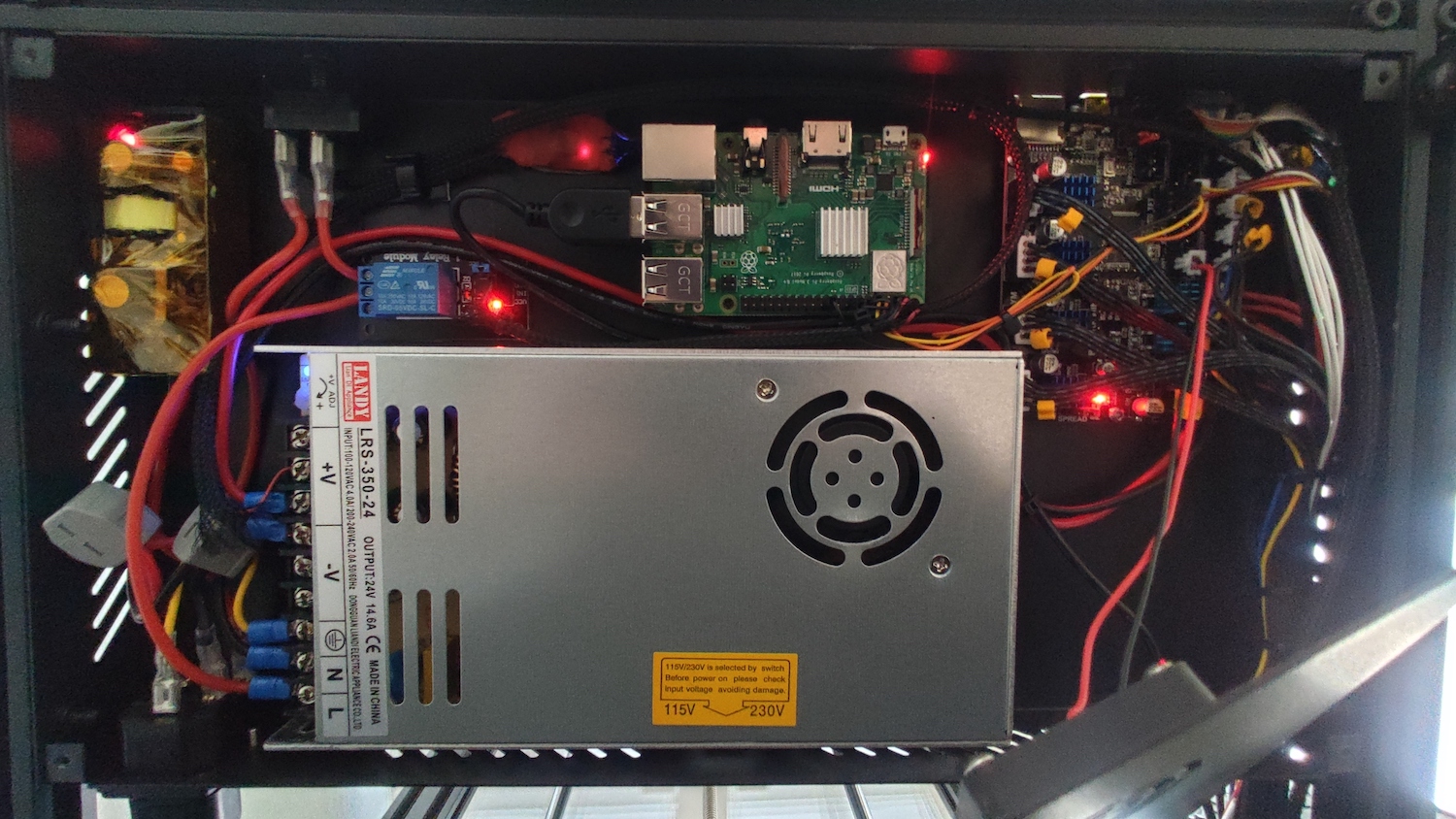
The RPI is mounted with this self printed mount you have to drill 4 holes to mount the plate to the case. The rest is fixed with strong double sided duct tape. The RPI has a direct UART connection to the board using the
enable_uart=1
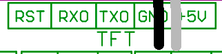
parameter inside the Octoprint /boot/config.txt and using the TFT header (RX0/TX0/GND) on the SKR Mini E3 as connection to the board.
This should work directly out of the box, because we’re using this parameter in Configuration.h:
/** * Select the serial port on the board to use for communication with the host. * This allows the connection of wireless adapters (for instance) to non-default port pins. * Note: The first serial port (-1 or 0) will always be used by the Arduino bootloader. * * :[-1, 0, 1, 2, 3, 4, 5, 6, 7] */
#define SERIAL_PORT 2
/** * Select a secondary serial port on the board to use for communication with the host. * This allows the connection of wireless adapters (for instance) to non-default port pins. * Serial port -1 is the USB emulated serial port, if available. * * :[-1, 0, 1, 2, 3, 4, 5, 6, 7] */
#define SERIAL_PORT_2 -1
The RPI UART wiring is simple, you have to use 3 wires, the own RPI UART RX/TX GPIO and one of the GND pins. So RX from the SKR Mini E3 TFT Header to TX (BCM 14) on the RPI and the TX from the SKR Mini E3 TFT Header to RX (BCM 15) on the RPI. For GND you can choose any GND Pin on the RPI. In the Octoprint settings you have to add the additional serial Port “/dev/ttyAMA0”
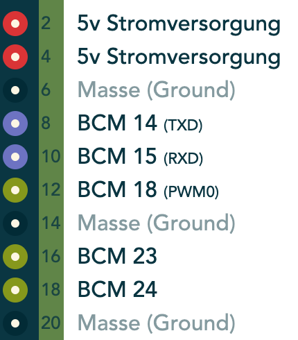
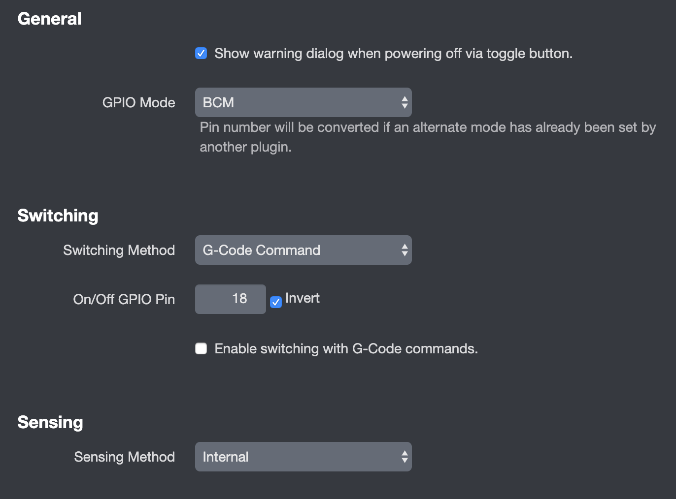
The Relay is powered by the RPI 5v feed and uses BCM 18 as control GPIO. You need the Octoprint Plugin “PSU Control” to control the Relay with Octoprint.
I’m also powering the RPI via GPIO. For that i’m using a AC 230v to DC 5v converter inside the box, which is connected directly from the first AC 230v incoming feed. On the RPI you can use any 5v and GND pin. So my RPI is always on. But keep in mind, every safety protection from the USB powering isn’t active if you power your RPI via GPIO! Advice: Buy a good quality AC / DC converter board.
The DC 24v to DC 5v converter is for a LED board, it’s a good light source for the print bed. You can connect the converter directly to the 24v PSU feeds or the 24v FAN output on the SKR Mini E3. I’ve used the 24v directly from the PSU.
Shopping List:
- BTT SKR Mini E3 v1.2
- 1 Channel 5v Relay Low Trigger
- DC 24v to DC 5v Converter
- Raspberry PI 3b (or 4b)
- Different color cables and Dupont Connector
- Genuine BLTouch v3.1
- WAGO Connectors
Downloads:
- Marlin 2.0 Bugfix Source
- Marlin 2.0 Binary
- Marlin 2.0 Binary (512k Edition with UBL and TMC Debug)

I can’t find any literature saying which pins are rx and tx on thr skr mini e3
Updated the post.
Very useful guide, tnx. With this connection, is the connection speed comparable to the usb normally used?
Looks good. good job. cool. I want one. I don’t think i will do it though because i want access to the sd card. My wifi pw changes from time to time and i would not want to have to take the printer apart due to that fact.